951-KLR-PAGES
The post ignition routine overview (timing changes and real-time fueling)
In the real-time ignition timing code discussion, we looked at how the speed sensor interrupt routine starts the dwell period and fires the spark. We left things there because that was the end of the story for generating the actual spark signal - but that wasn’t the end of that routine, and many other important things happen just after that point. These are things that, like the spark signal, need to be handled in real time, and are best just done after the spark fires.
As we would expect for real time code, this routine is mostly a consumer of things calculated elsewhere. Generally we won’t see how all these variables are calculated in this article, but I’ll add links to those when they’re documented.
Here, we’ll just discuss these things at a high level, and as usual there’s a code walkthrough if you want the gory details.
Outline
The over all sequence of events that happens in this routine is:
- move the current timing advance value (31h) towards its new target value (32h) according to some rules
- reset the reference sensor latch
- check if it’s time to do fuel injection:
- if it’s just after the second spark for this rev, then it’s definitely time to inject fuel
- if it’s just after the first spark, then it might be time to do a special supplementary injection
- check for the rev limit or any other fuel cut conditions (coasting, overload protection, all calculated elsewhere)
- apply any necessary transient fuel correction
- apply the low-rpm, cold acceleration enrichment if necessary
- add the injector latency (aka dead time) value from 54h to the final pulse
- turn the injectors on (the timer0 interrupt will turn them off later)
That’s a lot of stuff and it doesn’t fall neatly into the categories of fuel-related or timing-related etc. These are just the things that need to happen at this point!
Next we’ll discuss these things in a bit more detail (but still not to the level of reading code).
Timing adjustment
The main timing variable is 31h - this contains the angle BTDC at which the spark should fire (represented in half-tooth units of ~1.36 degrees). In the DME’s main loop, a new timing value is calculated using various maps. But this new value doesn’t simply overwrite 31h. Instead, the new value represents a target (stored in 32h), and a fairly involved set of rules determine how the current value is allowed to progress towards the target. This way, we never have sudden abrupt timing changes, which would be bad for smoothness and driveability.
The rules are implemented by a cascading set of flags. The flags are set and cleared elsewhere by various driving conditions, and in the routine we’re looking at now, they’re checked in the order shown below.
| flag | update frequency (34h) | update step size (r5) | effective rate (compared to no flags) |
|---|---|---|---|
| 22h.6 | 01 | 01 | 8x |
| 22h.5 | 01 | 02 | 16x |
| 22h.4 | 01 | 08 | 64x |
| None | 08 | 01 | 1x |
Each flag sets a particular update frequency and step size. The update frequency is the number of spark events to count before allowing the timing to change (counted via 34h). The step size is just how much the timing can change at once (measured as usual in flywheel half-teeth of 1.36 degrees).
For example, if 22h.6 is set, then timing is updated after every spark, by up to 1 half tooth. If 22h.6 is clear but 22h.5 is set, then the update frequency is still every time, but the change can be up to 2 teeth. This step size is an upper limit - the actual target value might be only one tooth away from the current value. So the actual adjustment made will be the step size or the difference, whichever is smaller.
Clearly, 22h.4 is by far the fastest regime, with with a maximum step size of 8 teeth (~10 degrees) after every spark (twice per rev). This can only happen if 22h.4 is set but 22h.5 and 22h.6 are both clear.
When all the flags are clear we get the slowest rule of all: one tooth at a time, every 8 events (i.e. 4 revs). This slow rule is the normal one - the others are applied in roughly these circumstances:
- 22h.4: below 800rpm or above a load value of 60
- 22h.5: while coasting, before fuel cut
- 22h.6: while applying fuel-reactivation correction
Ref sensor reset
There’s not much I can say about this simply because I haven’t been able to figure out the point. In the crank sensor signal article we saw that when the reference sensor’s digitized output is triggered by the S100 chip, it’s latched and won’t go high again until it’s reset. But the state of the ref sensor input to the 8051 is never read explicitly. It only triggers the external interrupt, and the 8051 interrupts are internally latched, and thus cannot be missed accidentally. So why doesn’t the S100 just make the output go high again once the raw sensor signal goes back below the threshold? I don’t know, but this section of the post-spark routine is where the 8051 asserts the reset line to the S100, putting the ref sensor digital signal back to the high state.
Check if we should do fuel injection
The general rule is that the injectors are fired once per revolution, after the second spark event. The way this is tracked is using the cylinder index variable 35h. It starts at zero and gets incremented after every spark, and reset when it gets to 2.
There are two conditions that break that general rule:
- cranking
- low-rpm cold acceleration enrichment
For the cranking situation, we fire the injectors after every spark event. The cranking flag 23h.2 gets cleared when rpm exceeds the temperature-dependent threshold in Map 3, which is 800rpm for most cases.
The second case is one of two kinds of acceleration enrichment (discussed in detail in the link above - the other kind discussed there doesn’t trigger this extra injection event). You can think of this low-rpm acceleration enrichment as being somewhat analogous to a carburettor pump-shot - it’s delivered just once but it should come as soon as possible when the airflow that triggers it is detected.
The need for this fuel shot is indicated by 21h.7. That flag gets set under certain acceleration conditions, and if we find now that it’s set just after the first spark, then we do a special injection event just for this. Normally when this happens, the entire injector pulse will be just whatever value the pump shot calls for. But it’s possible that the injectors might still be turned on from the previous injection event, and in that case we just add our pump shot value to the timer without stopping inejection.
Fuel cuts
There are various conditions that require fuel to be completely cut:
- rev limit exceeded
- coasting with the throttle closed
- overload protection
The last two of these are calculated in different places and the condition is signified by setting 23h.5. So here, we check if either the rev limit has been exceeded, or if 23h.5 is set for any reason, and if so then we bail out of this routine, skipping the whole fuel injector section completly.
Transient fuel correction
Generally when the throttle is at the idle position, and the rpm is above a certain threshold the fuel is turned off completlely. In fact this is a pretty complicated feature with quite a few rules. We won’t get too much into the details here, but there is a related condition that’s dealt with at this point: adjusting the fuel after it has been reactivated.
If this situation exists, it’s indicated by 21h.5, so that flag gates the whole section we’re about to look at. The details of how this flag gets set are documented in the fuel cut code walkthrough - right now we’ll see how it’s consumed.
Next, 21h.6 indicates whether or not the rpm returned to idle speed after fuel was cut. Based on the setting of 21h.6, we apply one of two corrections, which are best understood visually.
For idle fuel reactivation, we apply the changes from this map for the first few injection events:
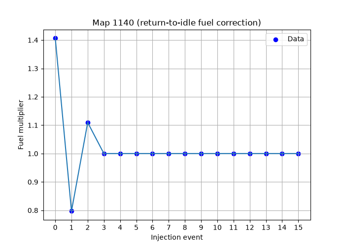
This has the effect of pulling the fuel pulse rich, then lean, then rich again (but less so), before settling down into having no effect towards the end.
For fuel reactivation that happens before the rpm sinks back to idle speed (for example gear changes), we use this map instead:
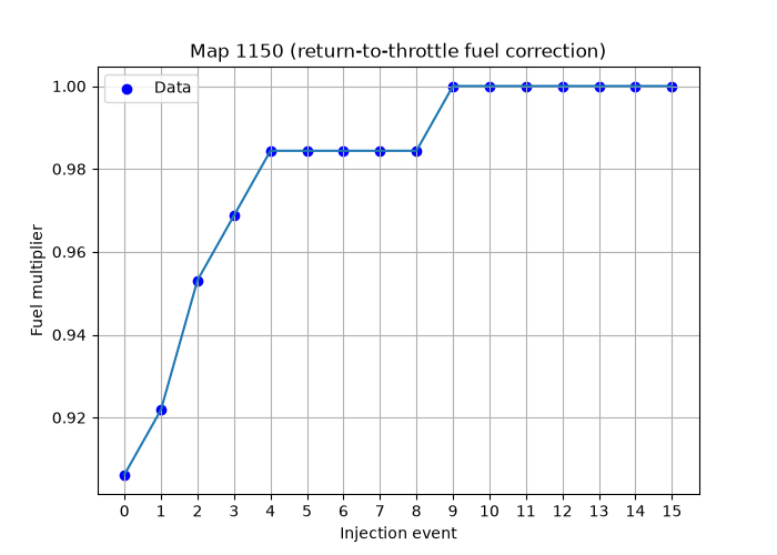
The actual effect of these corrections is easy to understand. Their purpose is a little harder to decipher, and the best I can do is a reasonable guess. In normal operation, there’s a film of fuel on the intake walls near the injectors, sometimes even a liquid pool. This fuel makes a contribution to the actual AFR (see the acceleration enrichment article for more details). When the throttle is closed, the lack of injection and the strong vacuum result in this fuel drying up completely. So when fuel is reactivated at idle, there might be a brief lean condition for a few cycles. Thus we might expect the correction to go rich for a few cycles. And ultimately that might be the net effect of Map 1140, but it may be that it’s necessary to go way too rich on the first cycle, then correct that on the next one, etc. This kind of thing probably had to be figured out by experimentation.
As for the other correction, Map 1150, well we know for certain that there’s a big overshoot in the AFM output signal when you open the throttle suddenly - that’s how acceleration enrichment works, by design. This overshoot is present when you reapply the throttle after a gear change, since you’re going from very low airflow back to at least the airflow you had before, maybe more. Again, experiments probably revealed that the first few cycles are just a bit too rich, and benefit from this gradual ramping up of the fuel.
Those are my best guesses, but I’m open to correction on the reasons for these corrections.
It’s worth taking a look at the behavior of the airflow meter during this gear change situation - this was done at wide open throttle:
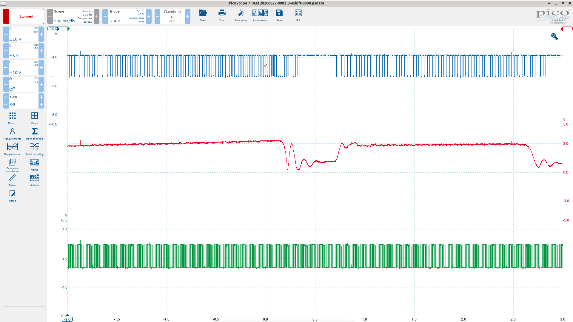
The blue trace is the fuel injector pulse, red is the AFM. You can ignore green here.
This shows the airflow ramping up during acceleration, then a severe oscillation as the throttle is closed. When the throttle is reapplied, we have another oscillation, overshooting quite a bit.
Zooming in and overlaying the 1150 map, we get some sense of what it does:
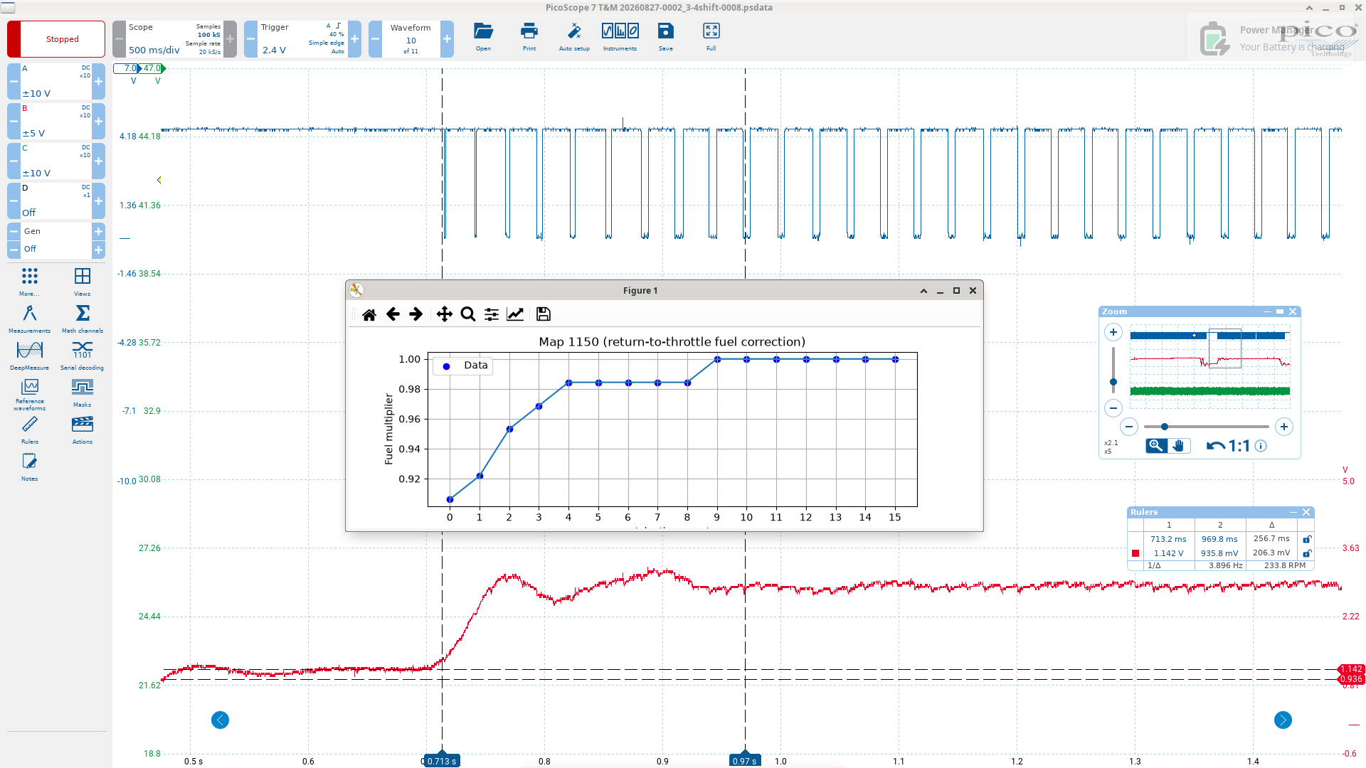
(You can ignore the cursors here, they’re not intended to measure anything meaningful in this image).
It seems like a very small correction, so this doesn’t shed much light on why its necessary, but it might help with making educated guesses.
Firing the injectors
The end of the routine in question is where the injectors are actually activated. The procedure here can be summarized as:
- if 21h.7 is set, add the acceleration enrichment value 4C to the main injector pulse
- add the voltage-based injector latency (x5) to the pulse
- complement the final pulse value
- clear the timer0 registers, load the value, and turn the injectors on (via p1.0)
- set 21h.2 as an injection on flag (we used this earlier for the extra injection event)
- tidy up before returning from the routine
The injector latency value is loaded from Map 26 into 54h in 040D, which is called after the main fuel enrichments routine (see the end of the code walkthrough of that section).
The input to the map is the system voltage and the map looks like this:
| 0x11 Battery voltage (V) | Value |
|---|---|
| 8 | 93 |
| 16 | 29 |
These values are multiplied by 5 here in the post ignition routine, and the timer ticks are 2us. So that means these values are hundreths of a ms, i.e. 0.93ms for 8v and 0.16ms for 16v (with the usual linear interpolation between those voltages).
This is the time it takes for the injector to open at the given voltage - the lower the voltage, the longer it takes for the injector to start delivering fuel!
The rest is very straightforward. We complement the final fuel pulse values, because the 8051 timers count up. Earlier, in the case where we were adding a special 4C enrichment to a pulse that was already on, we subtracted our pulse value from the timer value for the same reason.
When the timer overflows it triggers an interrupt, and the interrupt routine turns the injectors off by clearing p1.0, and clears the flag 21h.2.
Towards the end of this routine we also increment 4Dh, which is a counter that’s used to count injection events. This is used in the fuel enrichments to begin scaling back the cranking enrichment after 12 injections, and it’s also the counter that tracks the transient fuel adjustments described earlier (Maps 1140 and 1150). Here it gets incremented until it reaches 128. Stopping at this point is probably just a convenient way of making sure that it doesn’t overflow, since it might then deceive one of these fuel correction routines. Generally these routines set it to zero when they need to start counting.