951-KLR-PAGES
Hardware Overview
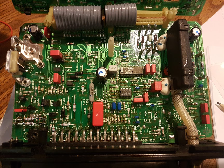
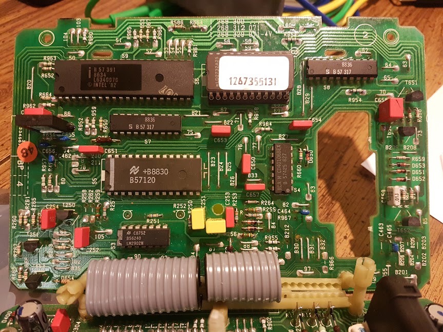
Here’s a pair of images showing the 2 circuit boards of the KLR. It might look like a lot but when you break it down there’s not that many components here. At the bottom of the first pic you can see the pins of the 25-way connector - that’s where the KLR connects to the engine harness.

On the right, the big black box with the tube connected to is the pressure sensor, or MAP (manifold absolute pressure) sensor - this is how the KLR knows the current boost pressure.
There are only 2 ICs of interest on this board: the 14-pin device is an LM2902M quad op amp, and the smaller 8-pin is a CA3080 OTA - operational transconductance amplifier (used by the knock sensor). This OTA is no longer made but there’s a little info available on it on the internet.

On the second board, from the top left, going right and down, we have
-
the Intel 8048 series microcontroller (the brains of the operation), clocked by an 11Mhz crystal
-
the removeable EEPROM with the program and maps
-
next there’s a couple of address bus latches that we don’t need to worry much about (marked “8836”).
-
halfway down on the left we have the 28-pin ADC0809 (an analog-to-digital converter)
-
to the right of the ADC is a CD40106 hex Schmitt trigger
-
below the ADC is another LM2902M quad op amp, identical to the one from the first board.
That covers it for integrated circuits! There’s a handful of transistors - most of them used for fairly obvious things - and after that, it’s pretty much all passive components.
We’ll get into how the various op amps, the OTA, and the ADC are used in great detail later. We won’t worry too much about the address latches, because their function is largely invisibe from a logical perspective: they enable communication between the 8048 and the EEPROM, but they’re controlled automatically by the 8048.
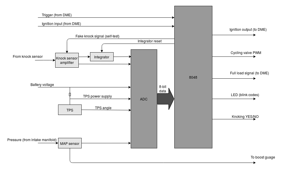
For now, in lieu of a proper schematic, here’s a very simple block diagram showing which signals go where with respect to the components discussed above:

It’s pretty much what you would expect, but there are a few interesting things worth noting:
-
there are 2 ADC channels dedicated to the knock sensor:
-
one indicates the general noise level from the knock sensor, and is used to detect a missing/damaged knock sensor, or a noisy engine. These conditions are associated with the blink codes described in the Technik document.
-
the other channel uses a resettable integrator (under the control of the 8048) to integrate the amplifier’s output over a window of around 15 degrees of crankshaft rotation; this is the one actually used to detect knock.
-
-
the KLR has a cool self-diagnostic feature: the 8048 can send a fake knock signal to the knock sensor amplifier to test it’s condition; if it consistently fails to detect knock from the integrator after doing this test repeatedly, the KLR will throw a blink code to indicate that it’s faulty. This is one of the many impressive features of the KLR.
-
there are also 2 channels dedicated to the throttle position sensor (TPS). One is the angle, as you’d expect, and the other is the supply voltage. There’s always a drop in the voltage supplied to the TPS, and it actually chages as the angle changes (since the amount of current that flows through the wiper into the ADC varies with the wiper angle). The 8048 always calcuales the angle output voltage as a proportion of the supply, so that variations in the supply won’t affect the accuracy.
This diagram is only intended to show the general outline of things; most of the inputs and outputs shown here merely as arrows are actually buffered and/or inverted through the Schmitt triggers, or through discrete transistors. The knock sensor amplifier uses no fewer than 7 op amps! But we’ll get into all that eventually.