951-KLR-PAGES
How the throttle position sensor is processed
Overview
The 951 has a throttle position sensor that looks a lot like the ones found in the non-turbo (NA) cars. But people are often surprised at the differences. The NA car’s throttle position sensor (more properly called a throttle position switch) just contains two microswitches - one that indicates when the throttle plate is at the idle position, and one to indicate when it’s at wide-open-throttle (WOT).
The turbo TPS on the other hand has just one microswitch, for idle, and a potentiometer that measures the exact position of the throttle. There’s no WOT switch. Upon seeing this one might assume, justifiably, that the DME uses the potentiometer to determine when the throttle angle should be regarded as WOT. But to the surpise of many people, the DME doesn’t see the signal from the pot at all! Instead, that signal comes here to the KLR. It’s the KLR that determines when the throttle is wide open, and it signals that to the DME with a high/low logic voltage signal (where low means we’re at WOT). Inside the DME, this signal is treated like the WOT microscwitch from the non-turbo cars.
The KLR triggers this WOT signal at a throttle angle of approximately 65 degrees. There is actually a map that allows this angle to be tuned by rpm, but its set to the same value for all rpm. This may give some insight into why the system works the way it does - Bosch/Porsche planned to take advantage of the ability to have a dynamic WOT angle, but abandoned the idea in the end.
So to summarize what is frankly a very confusing situation:
- the DME gets only the idle signal directly from the TPS
- the KLR gets only the actual throttle position, via the potentiometer
- the KLR decides when it’s time to signal WOT, and signals this to the DME via KLR pin 18/DME pin 3.
With that big picture stuff out of the way, we can turn to how the throttle position voltage is read and processed by the KLR code. It’s quite subtle and complicated, but hopefully the following walkthrough will clear things up.
Reading the raw values
If you refer to the block diagram in the Overview section, you’ll see that the TPS signal and power supply are both used as inputs to the KLR’s ADC. And from the pin assignments section you can see that channel 3 get the +v supply while channel 7 gets the actual potentiometer wiper output.
The reason for reading both is that the TPS has fairly low resistance and so there’s a significant voltage drop on the supply that varies depending on the wiper position. Thus the wiper position must be measured as a proportion of the current supply. We’ll see the details of how that works in the Processing section below.
The +v value is read in ADC Function #4 located at 44C. It’s stored into 39h and there’s not much else to say about the +v value at this point.
The signal value is a little more complicated. It uses channel 7 and if you look at the ADC code you’ll see that channel 7 is latched in ADC Function #6, after the MAP sensor value is read. But ch.7 is never read in this part of the code! That’s pretty confusing. The explanation is that it’s read at the start of the trigger routine when the KLR restarts. You won’t see any addressing taking place because the address was already latched from Function #6. The code from the trigger routine that handles the read is
0xa3 mov  r1,#$3C
0xa5 movx a,@r1
0xa6 xch  a,@r1
The movx instruction reads from an external location, in this case the ADC.
Note that the address specified by @r1 doesn’t actually have any effect because the ADC ch.7 address was latched already before the trigger reset. This is just used because the instruciton format requires something here.
From this code snippet we can see that 3C gets the TPS voltage signal value.
After this comes the code that checks the WOT threshold and sends the signal to the DME if appropriate, but we won’t look at that just yet because we’re not ready to really understand it until we trudge through the the processing of the raw ADC values, which we will do now.
Processing the raw values
Here we’ll examine how the raw TPS signal (3C) and power supply (39) values are processed for use throughout the KLR code. This process actually has two separate outputs that represent throttle position:
- 3A - the throttle position in degrees
- 43 - a value ranging from 0-27, used for cycling value control map lookups.
The raw TPS signal and power supply readings are processed in the routine that starts at A0F. This is called from the function list at 800, which in turns is called in a strange, indirect way from the routine at 2A3 after the blink code logic (using stack manipulation so that the ret statement “returns” to the next function in the list).
The processing logic deserves a high-level explanation. Earlier we touched on the fact that there’s a voltage drop in the supply that needs to be taken into account when interpreting the wiper position. In other words we want to get the output as a proportion of the supply. So you might expect that the final processed value will be input/supply. But it’s not quite so simple, because we have a few other concerns:
- we want to scale the input to convenient units
- we want to smooth out sudden changes in the power supply
In practice, all these goals are achieved by multiplying the raw TPS signal value by the fraction 3B/256. The trick is how 3B is calculated. It’s initialized to a starting value after the reset, but then adjusted based on the actual value of the TPS power supply (39h). The adjustment happens gradually over the course of a few engine cycles.
The part that concerns us now begins at A26:
0xa26 mov  r1,#$3C
0xa28 mov  a,@r1
0xa29 mov  r6,a
0xa2a dec  r1
0xa2b mov  a,@r1
0xa2c mov  r3,a
0xa2d sel  mb0
0xa2e call $0300
0xa30 sel  mb1
0xa31 dec  r1
0xa32 mov  @r1,a
The routine at 300 is an 8x8 multiply that uses r3 and r6 as inputs and returns the high byte of its output in a, and the low byte in r3. Frequently (as is the case here) only the high byte is used and the low byte is discarded. This is effectively a rough division by 256 (with the remainder discarded).
So the above code can be read as
a:r3 = 3C * 3B
3A ~= 3C * (3B/256)
The scaling numerator 3B is initialized to 119 in the trigger/reset routine. So the nominal scaling factor is 119/256, or about 0.46.
The next section sets the TPS map input value 43h:
0xa33 add  a,#$CB		;203
0xa35 jc   $0A38
0xa37 clr  a
0xa38 mov  r1,#$43
0xa3a mov  @r1,a
0xa3b mov  a,#$E3		;227
0xa3d add  a,@r1
0xa3e jnc  $0A42
0xa40 mov  @r1,#$1C
The logic here goes like this
if 3A < 53:
	43h = 0
else:
	43h = 3A + 203
if 43h > 28:
	43h = 28
So 43h ends up between 0 and 28, with 0 corresponding to a raw value of 3C=114. Later we’ll see that this means that only throttle values from around 57% and up are actually used for the cycling valve control maps.
Next comes the really interesting part, where the mysterious 3B is calculated:
0xa42 mov  r1,#$39
0xa44 mov  a,@r1
0xa45 mov  r6,a
0xa46 mov  r1,#$3B
0xa48 mov  a,@r1
0xa49 mov  r3,a
0xa4a sel  mb0
0xa4b call $0300
0xa4d sel  mb1
0xa4e add  a,#$A3		;163
0xa50 jz   $0A56
0xa52 cpl  a
0xa53 inc  a
0xa54 add  a,@r1
0xa55 mov  @r1,a
0xa56 ret
We can interpret this as
a = 39h * 3Bh/256
if a == 93: (this would mean 39h ~= 201 if 3B=119)
	return
else:
	3Bh = 39h - (a+163)
This is the trickiest part of the TPS logic to understand. The way to read the first part of the conditional statement above is that the program expects the power supply to be around 201 (that is, around 5v * 201/256 ~= 3.9v). The intial value of 3B is chosen with that assumption, and this will result in the high byte of the proudcut 39h * 3B being exactly 93. If the product differs from this, then 3B is gradually adjusted to make the high byte of the product 93. This means adjusting 3B upwards for lower power supply values, and vice-versa.
Now recall that the processed throttle angle 3A was calculated as 3C (raw value) multiplied by 3B/256. So if the power supply is lower than normal, the logic shown above will correct 3B upwards from 119, compensating and giving the same value of 3A for a given angle. The reverse happens then the power supply is higher than normal. Of course this happens after 3A is calculated, but this new value of 3B will be used the next time around.
It can be hard to visualize how the adjustment works and in particular, how many iterations it takes to get to the correct value. The following Python script simulates this logic and shows that for small deviations, 3B stabilizes at the corrected value after typically less than half a dozen cycles:
import sys

val_3B = 119

if __name__ == "__main__":
    val_39h = int(sys.argv[1])

    for i in range (0, 20):
        a = int((val_39h*val_3B)//256)
        if a == 93:
            print(val_3B)
            break
        else:
            a = (a+163) % 256
            val_3B = (val_3B - a) % 256
        print(val_3B)
Signalling WOT
Now that we have the details of how 3A is calculated, we’re in a position to revisit the WOT signalling logic that we skipped over earlier. It’s in the trigger/reset routine:
0xa9 mov  r1,#$3E
0xab mov  a,@r1
0xac cpl  a
0xad mov  r1,#$3A
0xaf add  a,@r1
0xb0 jc   $00B4
0xb2 anl  p1,#$DF		;11011111
We can read this as
if 3A <= 3E:
	WOT signal OFF (p1.5 LOW)
The port outputs are set to ON by default after a reset, so in fact the KLR always turns the WOT on briefly immediately after receiving the trigger signal from the DME. However, these brief pulses are filtered out by the KLR hardware so that the DME never sees them.
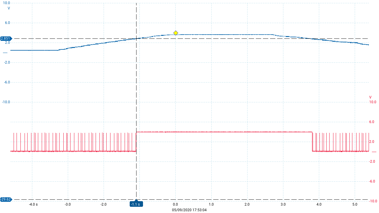
Here’s a signal trace showing this situation. The blue trace is the raw TPS signal voltage and the red trace is the WOT output pin. Here we can see the state just before and after the WOT condition is signalled to the DME - the brief (p1.5):
The following scope trace was captured from the DME side. Blue is the KLR trigger signal (that the DME sends to reset the KLR) and black is the WOT signal that the DME actually sees:
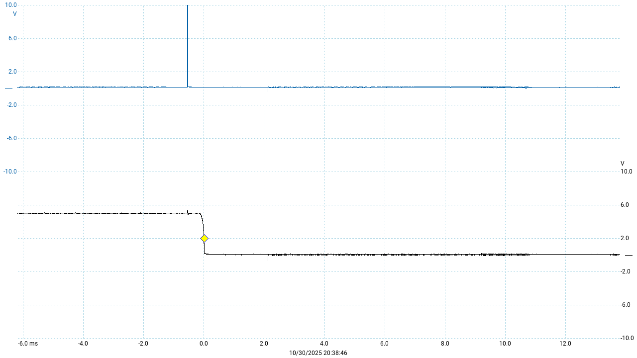
The pulse on the blue line here corresponds to one of the many short pulses in the red trace from the KLR trace in the previous image - but as you can see these pulses are not present in the actual WOT signal.
The code above turns the WOT off very soon after the reset if 3A is less than or equal to 3E. The value of 3E is determined by a a one-axis map (rpm) but the map has the value 66 for all entries.
So the minimum value that will trigger WOT is 67. Working backwards with the value 67 and the knowledge that the nominal conversion ratio is 119/256, we get
67 * 256/119 ~=144
So ~144 is the corresponding raw TPS signal value from 3C for the WOT threshold. We also saw earlier that the nominal power supply value is 201 (corresponding to about 3.9v).
And 144/201 = ~71.7%.
So now we know that the WOT threshold is around 72% throttle. Finally, 72% of 90 degrees is just under 65 degrees, so pretty close to the 65 deg. specified in the DME Test Plan.
Uses of the TPS
In the previous section we saw how the WOT threshold angle can be derived from the threshold value 66. We can use similar reasoning to determine that 43h ends up with the it’s range of 0-27 mapped to around 57%-86%. Thus for the purpose of the cycling valve control maps, throttle values below 57% are treated as 0 and values above 86% are treated as full throttle.
Both the values 3A and 43 are used extensively throughout the KLR code as map lookups and thresholds for knock control and error checking. We won’t go into the details of these uses here because understanding them generally requires a lot of background for the particular task being carried out. Instead, we’ll cover these uses of throttle position when they come up in the various routines.