951-KLR-PAGES
KLR master memory map
Byte variables
| Location | Purpose |
|---|---|
| 22h | angle to begin ADC initialization routine (in timer ticks) |
| 23h | angle to read ADC (after 22h, in timer ticks) |
| 24h | engine speed (complemented from r6; literally the number of 87us timer ticks per 180 degrees) |
| 2Eh | battery voltage |
| 2Fh | knock sensor (noise level diagnostics) |
| 34h | knock self-test failure count (starts at 6 and counts down, 0 triggers blink code) |
| 39h | throttle position (power supply) |
| 3Ah | throttle position (degrees) |
| 3Ch | throttle position (raw) |
| 3Fh | ?? |
| 38h | ?? |
| 41h | final CV duty cycle |
| 46h | knock sensor (proper) |
| 51h | target boost read from map |
| 52h | current MAP pressure |
| 53h | target boost, low-pass filtered (51h->55h->52h) |
| 55h:56h | intermediate target boost for filtering |
| 57h | boost reduction after knocking w/max timing retard |
| 58h:59 | filtered value related to 57h |
| 60h | boost control PID error (target boost - actual boost) |
| 61h | boost control PID I term (centered on 128) |
| 62h | boost control PID D term (spool assist, centered on 128) |
| 63h | boost control PID final output (2’s cpl signed) |
| 64h | D-term peak value |
| 65:66 | D-term filtered value (trails the peak to provide smooth decay) |
| 67h | boost control PID trim/slow-I term (centered on 128) |
| 68h | boost control feedforward value (CV duty cycle) |
| 33h | current blink code |
| 44h | rpm range (map axis 60 means < ~1842rpm, 0 means > 6068rpm) |
| 43h | throttle position (map axis; 0 means <53 deg., 1 means 53 deg., 28 means >= 81 deg.) |
| 70h - 73h | per-cylinder timing delay |
| 74h - 7Bh | per-cylinder knock threshold |
Blink Code Error Counters
| Location | Error Type |
|---|---|
| 30h | knock/MAP |
| 35h | boost high/low |
| 36h | TPS/TPS power supply |
Map locations
| Location | Map |
|---|---|
| C00h | target boost (8 throttle x 15 rpm, interpolated) |
| B00h | open loop cycling valve (8 throttle x 15 rpm, interpolated) |
| 992h | PID gain (4 throttle x 8 rpm, no interpolation, bit-packed) |
| 925h | RPM based constants (see below) |
RPM Dependant Constants
These are loaded from a series of 2D maps (rpm only) located at 0x925.
These maps have 9 entries each: the location into which the value is read followed by 8 value based on rpm range.
| Variable | Purpose |
|---|---|
| 0x2A | for calculating the angle to start ADC stuff (22h) |
| 0x2B | for calculating the angle for ADC read (23h) |
| 0x47 | coefficient for knock threshold (comparison with 46h) |
| 0x4A | cycle count before restoring 0.3 deg. timing (49h) |
| 0x50 | cycle count before restoring boost (15 to 37) |
| 0x4E | cycle count before pulling boost (31 to 125) |
| 0x4B | max timing retard (18 dec. for all rpm) |
| 0x48 | throttle position threshhold for knock control |
| 0x4C | threshold for pulling boost |
| 0x3E | angle for WOT (set to 66 decimal for all rpm) |
| 0x45 | minimum knock threshold value (10 for all rpm) |
| 0x69 | counter for 6A (set to 4 for all rpm) |
Units
Cycling valve PWM
The cycling valve PWM signal is handled by the timer interrupt routine, which runs at 87us ticks. Within the cycling valve logic in the timer interrupt routine, the on and off time are each maintained for a futher 4 counts. The period is 193, and 193*4*87 = 67164us which corresponds to ~14.8Khz. So that’s the PWM frequency, and the duty cycle values from the map can just be divided by 193. The final CV output processing caps the on time to 177, or about 92%.
Throttle position
Here’s some quick reference info; for a detailed explanation of the TPS processing logic, read this.
The variable 3Ah represents the throttle angle in degrees. But most of the code including map lookups use 44h. This is just the angles from 53 to 81 degrees mapped to the range 0-28, without scaling. Thus we have
| TPS angle (deg.) | 44h |
|---|---|
| 0 - 52 | 0 |
| 53 | 1 |
| 54 | 2 |
| … | … |
| 81 -90 | 28 |
So we have 29 values in total, with 0 meaning “below 53 deg.”. The remaining 28 values are the values that are actually used for the cycling valve PWM; there’s no CV activity below 53 degrees.
The maps typically use just 7 throttle angle values - this is achieved by just dividing 44h by 4 (rrc twice) before using it to look up a map value. But in many other places, 44h is used for threshold checks, and in those cases it’s generally used as the full 28-value range.
The wide-open-throttle signal is sent to the DME when 3A>= 66. That means WOT is active above 65 degrees. People frequently confuse degrees with percent. This angle is about 72% of the full throttle opening.
RPM
Reference info on the RPM range variable, 43h. More detail can be found in:
-
RPM Map Axis (Note: these measurements didn’t take account of the fact that there’s a few timer ticks of latency in the trigger routine before the raw speed measurement is processed, so they’re a little high - fixing that is on my to do list.)
The KLR code uses a map to convert the raw timer-ticks-per-180-degrees measurement (24h) into a value from 0-60, where 0 represents the highest rpm range and 60 the lowest. The rpm ranges are not evenly spaced! Instead, they’re smaller where the boost curve needs the best resolutoin, and larger where it’s mostly straight.
As with the TPS ranges, 0 is treated as a special one, leaving a total of 60 ranges, which can then be divided by 4 for map lookups, so that the maps actually have 15 rpm breakpoints.
Every time the trigger routine runs, it takes the value from the timer counter and stores it as the raw engine speed measurement, in 24h. But it doesn’t do this immediately. There’s a few dozen instructions first. It’s not worth counting exactly how many cycles there are - it’s about 2.6 timer ticks worth. These ranges I’ve shown below take account of that latency in the trigger routine, so they should be about as accurate as we can realistically get:
| Engine speed (RPM) | 44h | [24] ticks |
|---|---|---|
| 1832 - 1872 | 59 | 181 - 184 |
| 1872 - 1913 | 58 | 177 - 180 |
| 1913 - 1957 | 57 | 173 - 176 |
| 1957 - 2003 | 56 | 169 - 172 |
| 2003 - 2050 | 55 | 165 - 168 |
| 2050 - 2101 | 54 | 161 - 164 |
| 2101 - 2153 | 53 | 157 - 160 |
| 2153 - 2208 | 52 | 153 - 156 |
| 2208 - 2252 | 51 | 150 - 152 |
| 2252 - 2297 | 50 | 147 - 149 |
| 2297 - 2344 | 49 | 144 - 146 |
| 2344 - 2393 | 48 | 141 - 143 |
| 2393 - 2444 | 47 | 138 - 140 |
| 2444 - 2497 | 46 | 135 - 137 |
| 2497 - 2553 | 45 | 132 - 134 |
| 2553 - 2611 | 44 | 129 - 131 |
| 2611 - 2672 | 43 | 126 - 128 |
| 2672 - 2736 | 42 | 123 - 125 |
| 2736 - 2803 | 41 | 120 - 122 |
| 2803 - 2873 | 40 | 117 - 119 |
| 2873 - 2922 | 39 | 115 - 116 |
| 2922 - 2972 | 38 | 113 - 114 |
| 2972 - 3025 | 37 | 111 - 112 |
| 3025 - 3079 | 36 | 109 - 110 |
| 3079 - 3135 | 35 | 107 - 108 |
| 3135 - 3193 | 34 | 105 - 106 |
| 3193 - 3254 | 33 | 103 - 104 |
| 3254 - 3316 | 32 | 101 - 102 |
| 3316 - 3382 | 31 | 99 - 100 |
| 3382 - 3450 | 30 | 97 - 98 |
| 3450 - 3520 | 29 | 95 - 96 |
| 3520 - 3594 | 28 | 93 - 94 |
| 3594 - 3671 | 27 | 91 - 92 |
| 3671 - 3751 | 26 | 89 - 90 |
| 3751 - 3834 | 25 | 87 - 88 |
| 3834 - 3922 | 24 | 85 - 86 |
| 3922 - 4013 | 23 | 83 - 84 |
| 4013 - 4109 | 22 | 81 - 82 |
| 4109 - 4210 | 21 | 79 - 80 |
| 4210 - 4316 | 20 | 77 - 78 |
| 4316 - 4371 | 19 | 76 - 76 |
| 4371 - 4427 | 18 | 75 - 75 |
| 4427 - 4485 | 17 | 74 - 74 |
| 4485 - 4544 | 16 | 73 - 73 |
| 4544 - 4605 | 15 | 72 - 72 |
| 4605 - 4667 | 14 | 71 - 71 |
| 4667 - 4732 | 13 | 70 - 70 |
| 4732 - 4798 | 12 | 69 - 69 |
| 4798 - 4935 | 11 | 67 - 68 |
| 4935 - 5081 | 10 | 65 - 66 |
| 5081 - 5236 | 9 | 63 - 64 |
| 5236 - 5401 | 8 | 61 - 62 |
| 5401 - 5487 | 7 | 60 - 60 |
| 5487 - 5576 | 6 | 59 - 59 |
| 5576 - 5668 | 5 | 58 - 58 |
| 5668 - 5763 | 4 | 57 - 57 |
| 5763 - 5861 | 3 | 56 - 56 |
| 5861 - 5963 | 2 | 55 - 55 |
| 5963 - 6068 | 1 | 54 - 54 |
| 6068 and up | 0 | [24] <= 53 |
MAP
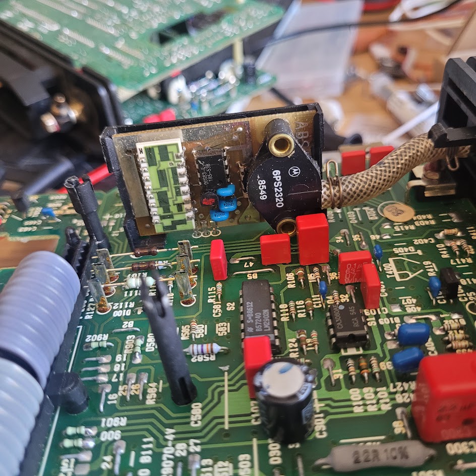
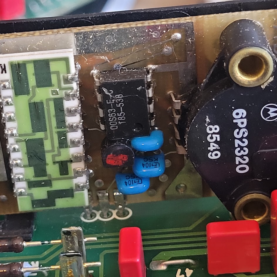
There are two different MAP sensors used in the KLRs. The early version used a daughter board with a Motorola transducer (probably an MPX200) along with various other componenets. The later version used a Bosch 0 273 003 204 200 (200kpa) sensor in a plastic case.
Here’s the early one:
And here’s the later Bosch one:
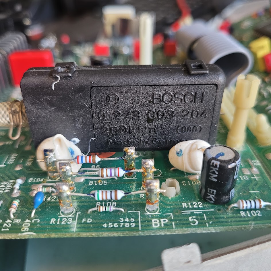
I’m not sure if they’re interchangeable. But the presence of those resistors installed on the standoffs suggest that they might have been hand picked to match the individual MAP sensor. The relevant code seems to be identical though.
There’s presumably no datasheet for the early one, being a custom design, but there is a datasheet for the later Bosch one. It gives a formula for the output voltage:
((4.55 * P_abs)/180) - 0.256
(assuming a 5v reference, which it has in the KLR).
So we should see ~2.271v for 100kpa.
The early one appears to be close to this. For instance, on an early version, at rest, I saw 2.21 - 2.24 from the map sensor, when the ambient pressure should have been in the neighborhood of 100kpa.
With both versions, the signal is reduced by a voltage divider and we see the value at Channel 4 (pin 2) at around ~0.94x the raw map sensor output. That would give us around 2.145v at the ADC input, or around 109 units.
Transfer function
I did some tests with some early KLRs I have (which I have numbered #2 and #3). I used a Mityvac and checked the calibration against a modern MAP sensor, a MPX4250.
Using KLR #3, we had 100kpa = 2.089v and 175kpa = ~3.87 (after correcting for the calibration of the mityvac based on the MPX4250) we can work out the slope and offset:
m = (3.872 - 2.089)/(175-100) = 0.02375
b = 2.089 - 100m ~= -0.286
Again, with the corrected data for KLR #2:
m = (3.906 - 2.115)/(175-100) = 0.02388
b = 2.115 - 100m ~= -0.272
So the 2 MAP sensors have essentially identical slope and the offset is about 13mv different, not enough to really matter.
The datasheet for the later Bosch sensor predicts
(((4.55 * 175)/180) - 0.256)
…and attenuating this by the divider ratio ~0.945 (based on comparing the sensor voltage to the ADC input voltage) gives 3.938, so very close. This would be about 1.5 units higher than the higher of the 2 early units, and about 3 units higher than the other one.
So my best guess here is that the early and late sensors are intended to have exactly the same transfer function, and my examples vary a bit, almost entirely in the offset.
So we know the offset is in the order of 14 units (hard to say if the Bosch offset is deliberately lower or just tolerance) and we also add 10 in the MAP routine. So the final offset is -4 units.
This comes out to something like
x = 1.22 * P - 4
where P is pressure in kpa and x is ADC units
Then
P = (x+4) / 1.22
For example, we know that KLR #3 showed 3.872v for 175kpa, s;
>>> 256 * (3.872/4.985)
198.84292878635907
Then the MAP routine adds 10 to get 208.8
Using our formla:
>>> 1.22 * 175-4
209.5
The discrepancy is due to the fact that 4 is an approximation for the offset, since we have variations in the real values and the Bosch datasheet.
Putting all this together gives us something very close to 1kpa = 1.22 units in the software. Here are some important numbers assuming that’s true:
- overboost threshold: 32 = 0.26 bar
- underboost threshold: 55 = 0.45 bar (early KLR) 64 = 0.53 bar (late KLR)
- boost reduction for knock: 5 = 0.042 bar
(The service manual quotes exactly 0.45 as the underboost threshold. The Technik document doesn’t specify over/underboost thresholds but does say that boost reduction for knock is “taken back in steps of 30 to 50 mbar (0.030 to 0.050 bar)….”.
Maps
Boost
- ‘86:
| Throttle% \ RPM | 0 | 1864 | 2041 | 2254 | 2446 | 2674 | 2948 | 3164 | 3415 | 3708 | 4057 | 4479 | 4724 | 4998 | 5653 | 6050 |
|---|---|---|---|---|---|---|---|---|---|---|---|---|---|---|---|---|
| 57.0 | 137 | 141 | 144 | 145 | 145 | 146 | 146 | 148 | 148 | 148 | 150 | 150 | 150 | 152 | 152 | 152 |
| 61.3 | 139 | 141 | 145 | 151 | 154 | 157 | 157 | 158 | 158 | 158 | 158 | 158 | 158 | 158 | 158 | 158 |
| 65.6 | 139 | 141 | 148 | 157 | 164 | 167 | 167 | 170 | 170 | 170 | 167 | 167 | 166 | 165 | 165 | 165 |
| 69.9 | 141 | 142 | 159 | 170 | 177 | 180 | 180 | 180 | 180 | 180 | 177 | 177 | 174 | 171 | 171 | 171 |
| 74.2 | 143 | 145 | 171 | 183 | 190 | 190 | 190 | 190 | 190 | 190 | 188 | 185 | 180 | 178 | 177 | 177 |
| 78.5 | 145 | 152 | 180 | 204 | 203 | 202 | 201 | 201 | 200 | 199 | 197 | 193 | 186 | 182 | 180 | 180 |
| 82.8 | 145 | 152 | 180 | 204 | 203 | 202 | 201 | 201 | 200 | 199 | 197 | 193 | 186 | 182 | 180 | 180 |
| 87.1 | 145 | 152 | 180 | 204 | 203 | 202 | 201 | 201 | 200 | 199 | 197 | 193 | 186 | 182 | 180 | 180 |
- ‘87:
| Throttle% \ RPM | 0 | 1864 | 2041 | 2254 | 2446 | 2674 | 2948 | 3164 | 3415 | 3708 | 4057 | 4479 | 4724 | 4998 | 5653 | 6050 |
|---|---|---|---|---|---|---|---|---|---|---|---|---|---|---|---|---|
| 57.0 | 137 | 141 | 144 | 145 | 145 | 146 | 146 | 148 | 148 | 148 | 150 | 150 | 150 | 152 | 152 | 152 |
| 61.3 | 139 | 141 | 145 | 151 | 154 | 157 | 157 | 158 | 158 | 158 | 158 | 158 | 158 | 158 | 158 | 158 |
| 65.6 | 139 | 141 | 148 | 157 | 164 | 167 | 167 | 170 | 170 | 167 | 167 | 167 | 166 | 165 | 165 | 165 |
| 69.9 | 141 | 142 | 159 | 170 | 177 | 180 | 180 | 180 | 180 | 177 | 176 | 175 | 174 | 171 | 171 | 171 |
| 74.2 | 143 | 145 | 171 | 190 | 193 | 193 | 193 | 193 | 193 | 191 | 188 | 186 | 184 | 182 | 180 | 180 |
| 78.5 | 145 | 152 | 180 | 206 | 208 | 209 | 208 | 207 | 207 | 206 | 202 | 198 | 193 | 188 | 185 | 185 |
| 82.8 | 145 | 152 | 180 | 206 | 208 | 209 | 208 | 207 | 207 | 206 | 202 | 198 | 193 | 188 | 185 | 185 |
| 87.1 | 145 | 152 | 180 | 206 | 208 | 209 | 208 | 207 | 207 | 206 | 202 | 198 | 193 | 188 | 185 | 185 |
- ‘89/S:
| Throttle% \ RPM | 0 | 1864 | 2041 | 2254 | 2446 | 2674 | 2948 | 3164 | 3415 | 3708 | 4057 | 4479 | 4724 | 4998 | 5653 | 6050 |
|---|---|---|---|---|---|---|---|---|---|---|---|---|---|---|---|---|
| 57.0 | 137 | 141 | 144 | 145 | 145 | 146 | 146 | 148 | 148 | 148 | 150 | 150 | 150 | 152 | 152 | 152 |
| 61.3 | 139 | 141 | 145 | 151 | 154 | 157 | 157 | 158 | 158 | 158 | 158 | 158 | 158 | 158 | 158 | 158 |
| 65.6 | 139 | 141 | 148 | 157 | 164 | 167 | 167 | 170 | 170 | 167 | 167 | 167 | 166 | 165 | 165 | 165 |
| 69.9 | 141 | 142 | 159 | 170 | 177 | 180 | 180 | 180 | 180 | 177 | 176 | 175 | 174 | 171 | 171 | 171 |
| 74.2 | 143 | 145 | 171 | 190 | 193 | 193 | 193 | 193 | 193 | 191 | 188 | 186 | 184 | 182 | 180 | 180 |
| 78.5 | 145 | 152 | 180 | 206 | 206 | 206 | 206 | 206 | 206 | 208 | 206 | 206 | 206 | 206 | 206 | 194 |
| 82.8 | 145 | 152 | 180 | 206 | 206 | 206 | 206 | 206 | 206 | 208 | 206 | 206 | 206 | 206 | 206 | 194 |
| 87.1 | 145 | 152 | 180 | 206 | 206 | 206 | 206 | 206 | 206 | 208 | 206 | 206 | 206 | 206 | 206 | 194 |
Cycling valve duty cycle:
- ‘86
| Throttle% \ RPM | 0 | 1864 | 2041 | 2254 | 2446 | 2674 | 2948 | 3164 | 3415 | 3708 | 4057 | 4479 | 4724 | 4998 | 5653 | 6050 |
|---|---|---|---|---|---|---|---|---|---|---|---|---|---|---|---|---|
| 57.0 | 38 | 38 | 38 | 38 | 38 | 38 | 38 | 38 | 38 | 38 | 38 | 38 | 38 | 38 | 38 | 38 |
| 61.3 | 57 | 57 | 57 | 57 | 57 | 57 | 57 | 57 | 57 | 57 | 57 | 54 | 54 | 48 | 48 | 48 |
| 65.6 | 76 | 76 | 76 | 76 | 76 | 76 | 76 | 76 | 76 | 73 | 73 | 69 | 67 | 61 | 58 | 58 |
| 69.9 | 115 | 115 | 115 | 115 | 115 | 109 | 108 | 106 | 104 | 100 | 96 | 86 | 76 | 73 | 69 | 77 |
| 74.2 | 154 | 154 | 154 | 154 | 138 | 125 | 121 | 117 | 115 | 111 | 108 | 102 | 94 | 88 | 81 | 92 |
| 78.5 | 191 | 191 | 191 | 175 | 161 | 148 | 144 | 138 | 134 | 129 | 125 | 121 | 109 | 104 | 100 | 115 |
| 82.8 | 191 | 191 | 191 | 175 | 161 | 148 | 144 | 138 | 134 | 129 | 125 | 121 | 109 | 104 | 100 | 115 |
| 87.1 | 191 | 191 | 191 | 175 | 161 | 148 | 144 | 138 | 134 | 129 | 125 | 121 | 109 | 104 | 100 | 115 |
- ‘87 and ‘89/S:
| Throttle% \ RPM | 0 | 1864 | 2041 | 2254 | 2446 | 2674 | 2948 | 3164 | 3415 | 3708 | 4057 | 4479 | 4724 | 4998 | 5653 | 6050 |
|---|---|---|---|---|---|---|---|---|---|---|---|---|---|---|---|---|
| 57.0 | 38 | 38 | 38 | 38 | 38 | 38 | 38 | 38 | 38 | 38 | 38 | 38 | 38 | 38 | 38 | 38 |
| 61.3 | 57 | 57 | 57 | 57 | 57 | 57 | 57 | 57 | 57 | 57 | 57 | 54 | 54 | 48 | 48 | 48 |
| 65.6 | 76 | 76 | 76 | 76 | 76 | 76 | 76 | 76 | 76 | 73 | 73 | 69 | 67 | 61 | 58 | 58 |
| 69.9 | 115 | 115 | 115 | 115 | 115 | 109 | 108 | 106 | 104 | 100 | 96 | 90 | 84 | 81 | 81 | 81 |
| 74.2 | 154 | 154 | 154 | 154 | 154 | 146 | 142 | 138 | 134 | 131 | 127 | 123 | 119 | 115 | 115 | 115 |
| 78.5 | 191 | 191 | 191 | 191 | 191 | 182 | 173 | 169 | 165 | 161 | 157 | 150 | 146 | 142 | 146 | 150 |
| 82.8 | 191 | 191 | 191 | 191 | 191 | 182 | 173 | 169 | 165 | 161 | 157 | 150 | 146 | 142 | 146 | 150 |
| 87.1 | 191 | 191 | 191 | 191 | 191 | 182 | 173 | 169 | 165 | 161 | 157 | 150 | 146 | 142 | 146 | 150 |
PID gain
- all models:
| Throttle% \ RPM | 1864 | 2254 | 2674 | 3164 | 3708 | 4479 | 4998 | 6050 |
|---|---|---|---|---|---|---|---|---|
| 57.0 | 227 | 227 | 231 | 234 | 230 | 230 | 233 | 233 |
| 65.6 | 227 | 195 | 167 | 138 | 134 | 166 | 169 | 201 |
| 74.2 | 227 | 131 | 103 | 106 | 102 | 134 | 137 | 169 |
| 82.8 | 227 | 163 | 103 | 106 | 102 | 134 | 169 | 201 |